EN
EN English
 Español
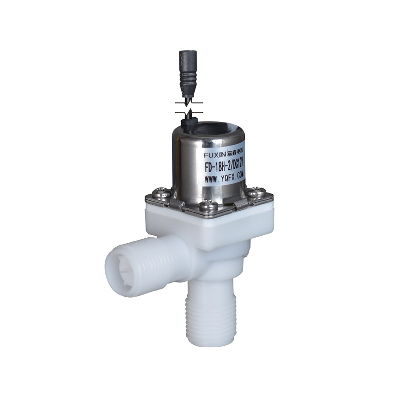
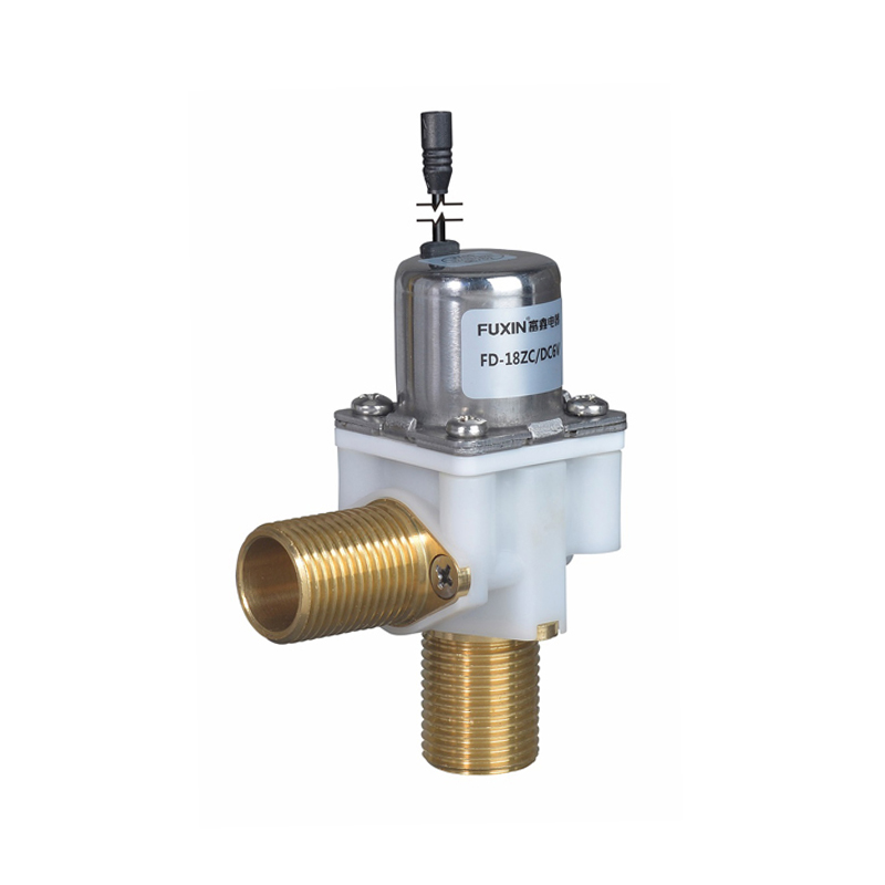
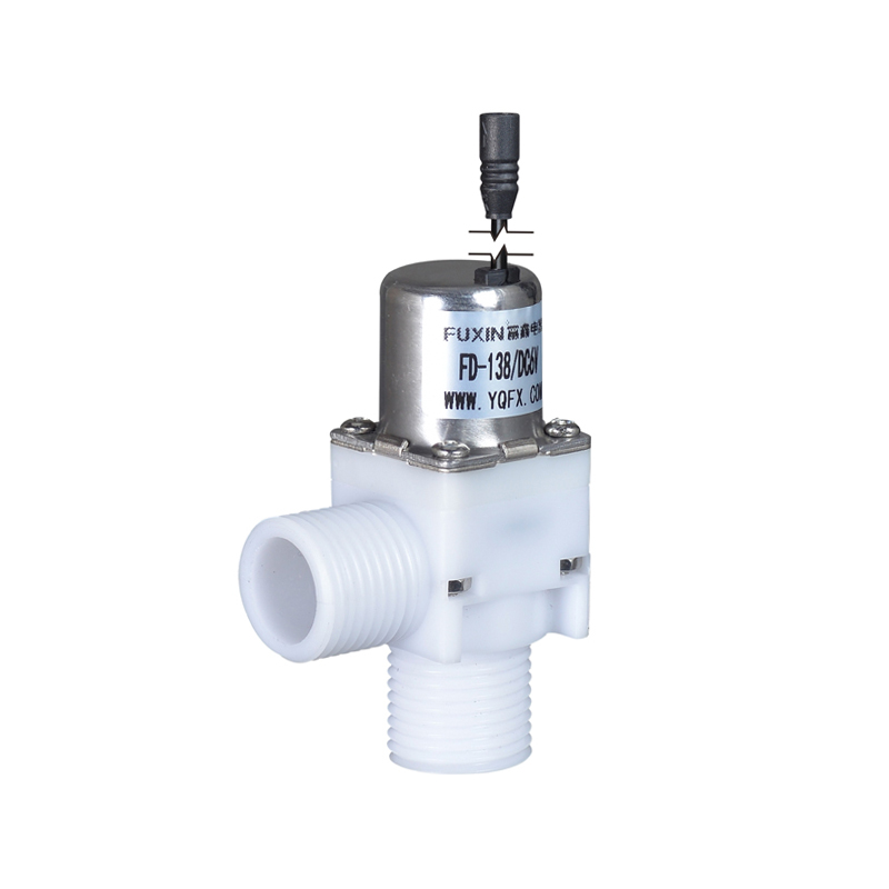
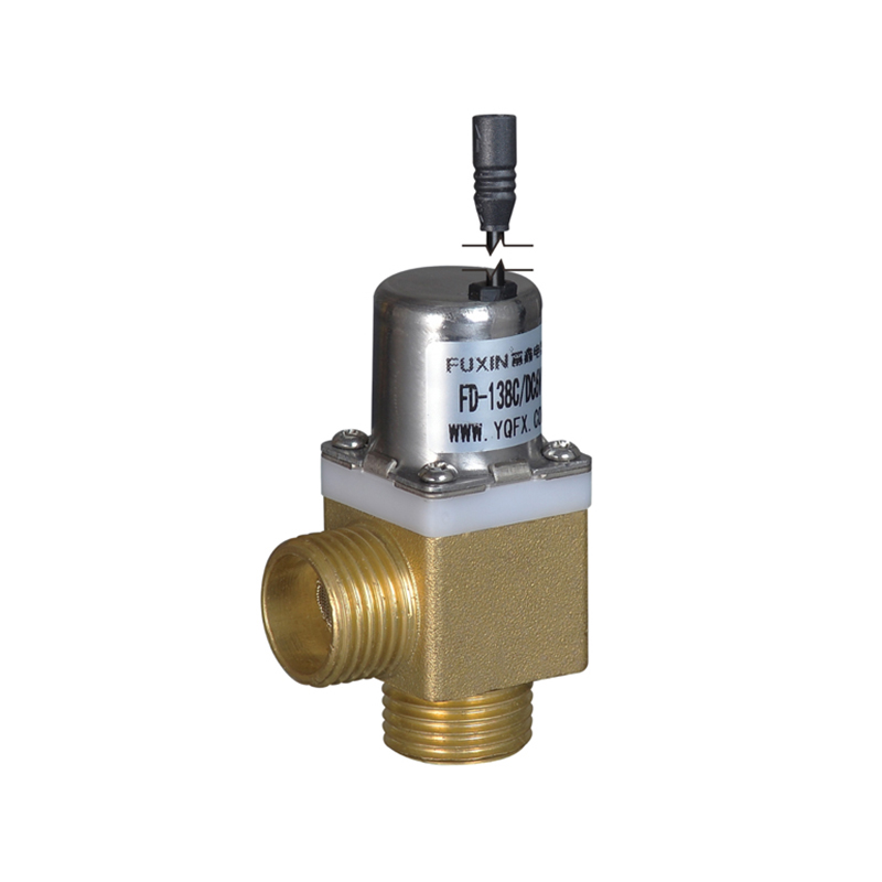
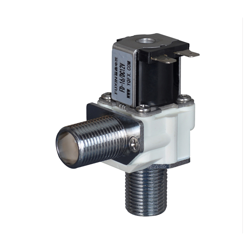
In systems that rely on solenoid valves for flow control, continuous power draw is often treated as an unavoidable operating cost. The valve holds its position, the coil stays energized, and the power meter runs. Over weeks and months, that baseline consumption compounds — raising energy bills, generating heat in enclosed enclosures, and accelerating wear in components that were not designed for indefinite energization. A Bi Stable Solenoid Valve approaches this problem from a different starting point: instead of requiring sustained power to maintain position, it uses a pulse to switch and then holds that position without any further electrical input.
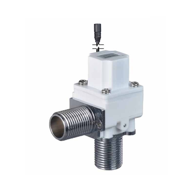
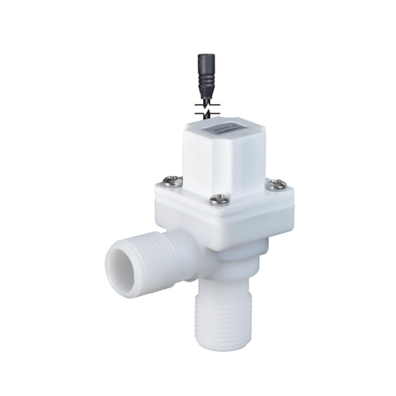
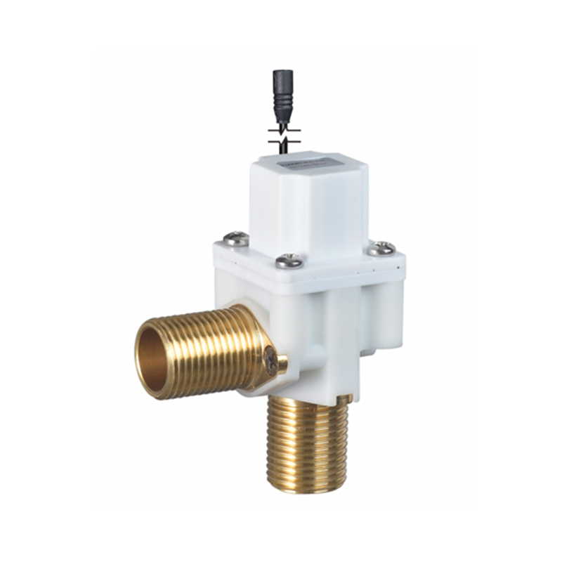
What a Bi Stable Solenoid Valve Is and How It Differs from Conventional Designs
The Two-State Holding Mechanism
A conventional solenoid valve requires a continuous current to keep the plunger in the actuated position. Remove the current and the spring returns the valve to its default state. The electromagnetic force and the spring force are in constant opposition while the valve is held open or closed.
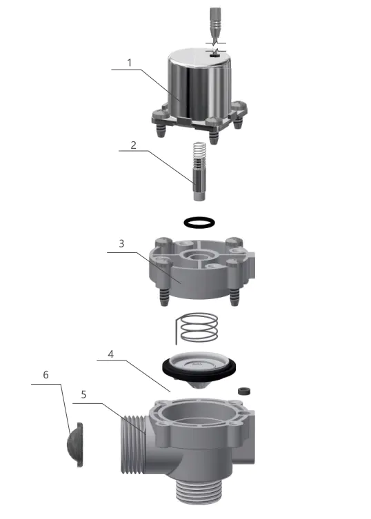
A latching solenoid valve replaces this continuous opposition with a permanent magnet mechanism. A permanent magnet holds the plunger in position after the switching pulse ends. Two stable states exist — open and closed — and the valve remains in whichever state it was last switched to without any power input. A brief pulse of opposite polarity releases the latch and switches the valve to the other state.
Why the Name Reflects the Operating Principle
The term "bi stable" refers directly to this two-state latching behavior. Unlike a monostable valve that has one default position and must be continuously powered to maintain the other, this type of valve is genuinely stable in both positions. Power is consumed only at the moment of transition — the rest of the time, the valve draws nothing.
The Root Cause of Continuous Power Consumption in Standard Valves
Coil Energization Is the Source
In a standard solenoid valve, the electromagnetic coil must be kept energized to maintain the actuated position against the return spring. This means current flows through the coil resistance for the entire duration the valve is held in that state — which, in many applications, is hours or days at a time.
The power dissipated in the coil appears as heat. In enclosed panels, control cabinets, or densely packed valve manifolds, this heat accumulates and must be managed through cooling, ventilation, or derating of nearby components.
Does the Problem Get Worse at Scale?
Yes — and the effect compounds. A single valve drawing a small continuous current is manageable. A system with dozens of valves, each drawing that current whenever actuated, creates a substantial sustained load. For battery-powered systems, remote installations, or facilities with high energy costs, this baseline consumption becomes a design constraint rather than a background detail.
The challenge is not just the energy cost — it is what the heat and sustained current do to the valve itself. Prolonged coil energization raises the coil temperature, which accelerates insulation degradation and increases the likelihood of coil failure over time.
How the Latching Mechanism Eliminates Continuous Draw
Pulse-Driven Switching
The switching event in this type of valve is brief. A short electrical pulse generates enough electromagnetic force to overcome the permanent magnet holding force and move the plunger from one stable position to the other. Once the plunger reaches its new position, the permanent magnet holds it there.
The electrical system then removes the pulse. The valve stays in the new position with zero power consumption. The coil is not energized. No heat is generated. No current flows.
Fail-Safe Behavior Depends on Application Design
One characteristic of bi stable designs that engineers need to account for is the absence of a default spring-return position. In a standard normally-closed valve, removing power automatically closes the valve — a behavior relied upon in many safety-critical systems.
A latching valve does not have this default behavior. It holds its last position regardless of power state. For applications where a defined failure mode is required, the control system must issue an explicit switching pulse before power is removed. This needs to be factored into system design rather than treated as a limitation — it is a design choice with specific implications for how the control logic operates.
Applications Where Bi Stable Performance Offers a Practical Advantage
Battery-Powered and Remote Systems
Systems that operate from batteries or limited power supplies are where the energy consumption difference becomes immediately significant. Remote irrigation controllers, mobile fluid handling units, and portable monitoring equipment all share the same constraint: available power is limited and must be managed carefully.
A latching valve fits naturally into these systems because the power demand is predictable and brief. The battery supplies a pulse at each switching event and is otherwise not loaded by the valve. Over extended deployment periods — weeks or months between maintenance visits — this difference in power draw directly extends battery life.
IoT and Smart Infrastructure Applications
In smart building systems, water management networks, and connected industrial automation, valve states may hold for extended periods between commanded changes. A sensor-driven irrigation zone may stay open for a defined period and then close until the next cycle — potentially hours or days later.
In these applications, a conventional solenoid valve draws power for the entire open period. A latching design draws power only at the two transition points. For a network of dozens or hundreds of controlled points, this reduction in sustained current draw simplifies power supply sizing and reduces infrastructure costs.
HVAC and Building Automation
Zone control valves in HVAC systems frequently hold a fixed state — open during occupied hours, closed during unoccupied periods — with relatively infrequent switching. Conventional zone valves energize throughout the holding period. Bi stable designs reduce this to brief switching pulses, which lowers both energy consumption and heat generation in control panels that may contain many such valves.
For facilities with building management system integration, the short switching pulse also simplifies the drive electronics — a brief pulse driver requires less thermal management than a sustained current driver.
Fluid Control in Industrial Automation
Process control applications that involve long valve hold times benefit from the same principle. Batch processes, fill-and-hold sequences, and monitoring-triggered flow control all involve valves that may be commanded to one position and held there for a defined process period.
Where valve actuation is infrequent but hold times are long, the energy and thermal benefits of a bi stable design scale with the hold time. A valve held open for four hours in a conventional design consumes energy for four hours. The bi stable equivalent consumes energy for the two switching pulses only.
Comparing Bi Stable and Conventional Solenoid Valve Designs
The table below outlines the key operational differences between conventional and latching solenoid valve designs across the parameters that matter for system specification.
| Parameter | Conventional Solenoid Valve | Latching (Bi Stable) Design |
|---|---|---|
| Power during hold | Continuous current required | Zero — position maintained by permanent magnet |
| Heat generation | Sustained coil heating during hold | Minimal — only during switching pulse |
| Failure mode on power loss | Returns to spring default (NO or NC) | Holds last position |
| Drive electronics | Sustained current driver | Pulse driver (simpler thermal requirements) |
| Battery suitability | Limited by continuous draw | Well-suited — only switching events draw current |
| Switching speed | Continuous readiness | Brief pulse required — response time accounts for pulse duration |
| Coil longevity | Thermal stress from sustained energization | Lower thermal stress — longer service life expected |
| Suitable hold duration | Short to medium | Any duration — no penalty for long holds |
Selecting between the two designs depends on the hold duration profile, the power supply constraints, the failure mode requirements, and the operating environment. Neither design is universally applicable — the specification should follow from the application parameters.
System Integration Considerations
Drive Electronics Must Generate a Controlled Pulse
The control system for a latching valve needs to generate a defined switching pulse rather than simply toggling a sustained output. Many industrial PLCs and microcontroller-based systems can generate timed pulses through standard output timing configuration, but this requires explicit attention during system design.
The pulse polarity, duration, and voltage must be matched to the valve specification. Underpowered pulses may not fully switch the valve. Overpowered pulses may exceed the coil rating. The drive circuit should be specified alongside the valve, not as an afterthought.
Position Feedback for Critical Applications
Because a latching valve does not have a default spring return, the control system cannot assume a known valve state after a power interruption or communication failure. For critical applications, position feedback — through a limit switch, flow sensor, or other confirmation method — provides the system with verified state information rather than assumed state.
This is standard practice in well-designed fluid control systems regardless of valve type, but it becomes more important in bi stable applications where the valve will hold its pre-failure position indefinitely.
Wiring and Coil Polarity
Switching a latching valve requires reversing the current direction through the coil to move between the two stable states. This means the drive circuit needs to be capable of generating pulses of both polarities — either through an H-bridge arrangement, two separate coil windings, or a dual-output pulse driver.
Wiring the drive circuit correctly at installation prevents switching failures and protects the coil from incorrect energization. This is a commissioning step that should be verified before the system goes live.
Evaluating Bi Stable Solenoid Valves for a Specific Application
Before specifying a latching valve for a system, the following questions help identify whether the design is appropriate and which configuration is needed:
- What is the typical hold duration between switching events? Longer hold times favor bi stable designs more strongly.
- What is the power supply type and capacity? Battery or limited-supply systems benefit significantly from pulse-only operation.
- Is a defined failure position required? If yes, the control logic must address this explicitly.
- What drive electronics are available or planned? The control system must support pulse generation of the correct polarity and duration.
- What flow medium is being controlled, and are there temperature, pressure, or chemical compatibility requirements? These parameters affect valve body and seal material selection independent of the actuation type.
Sourcing and Technical Support for Bi Stable Solenoid Valve Applications
Selecting the right Bi Stable Solenoid Valve for a specific application involves more than choosing between a conventional and latching design. The body material, seal compatibility, flow rating, pressure rating, connection type, coil voltage, and drive pulse specification all need to match the system requirements. Working with a manufacturer who can discuss these parameters in the context of the application reduces the risk of misspecification. Zhejiang Fuxin Electrical Technology Co., Ltd. manufactures Bi Stable Solenoid Valves and related fluid control components for industrial, HVAC, irrigation, and IoT applications. Their product range covers a variety of flow media, connection configurations, and coil voltage options, with engineering support available to help match valve specifications to system requirements. If you are evaluating bi stable designs for a current or planned application, reaching out with your application parameters — flow medium, pressure, hold duration, and power supply type — gives their team the context to recommend a configuration suited to your system.