
 EN
 English
 Español



An automated flush depends on several parts working in sequence. A controller sends a command, the wiring carries it, and the valve opens or closes the water path. Each part can look suitable on its own, yet the assembly may still fail to operate as intended if they do not match.
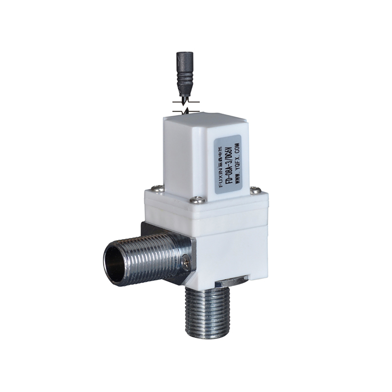
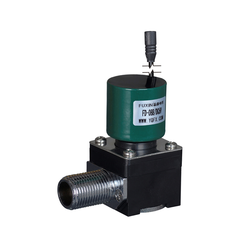
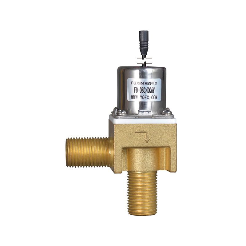
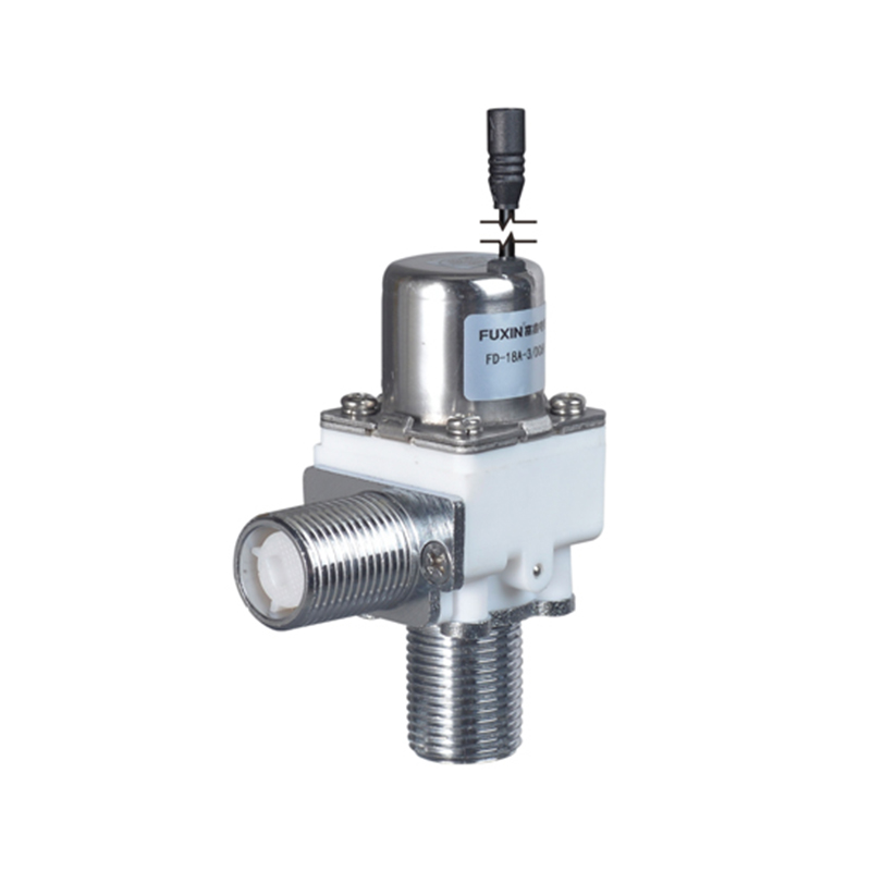
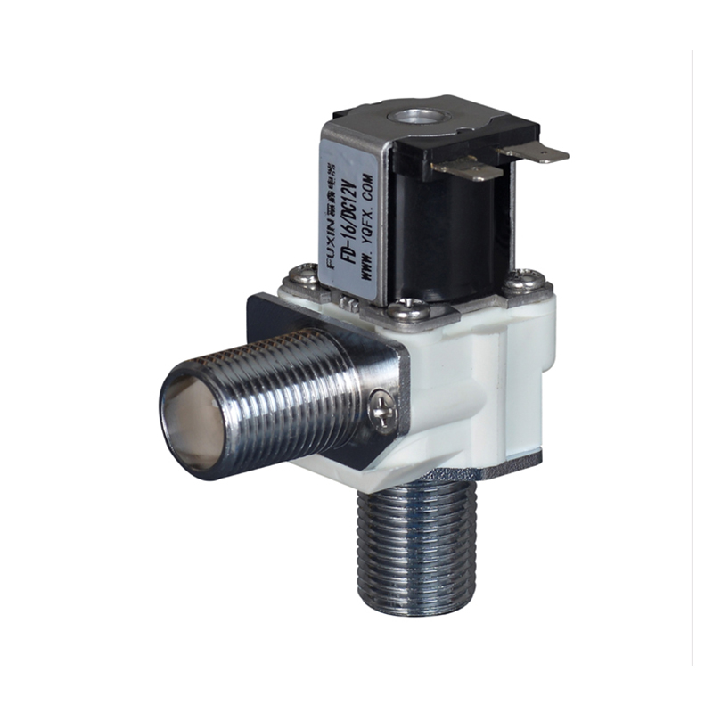
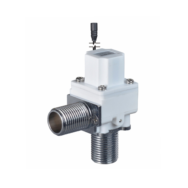
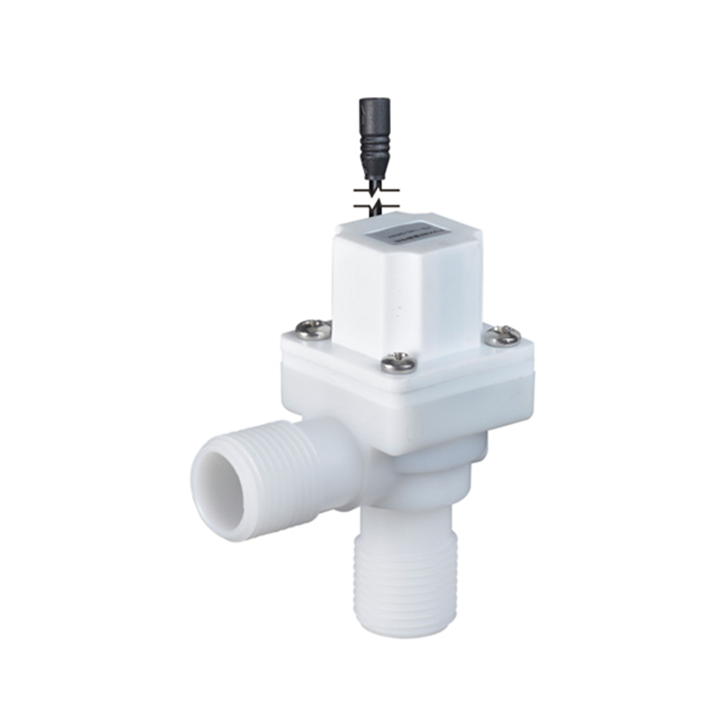
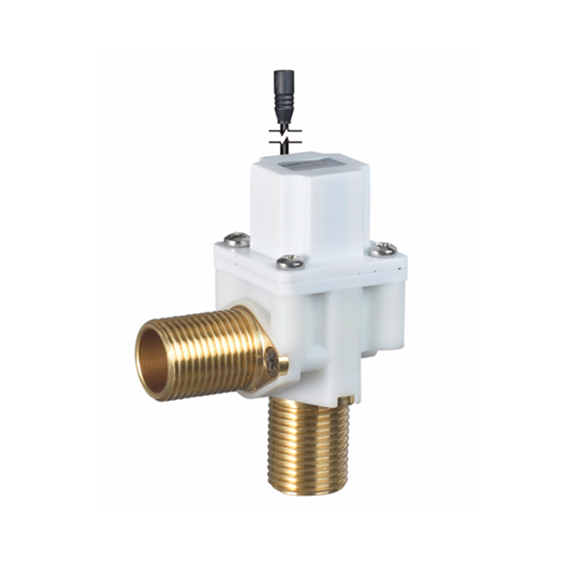
A Solenoid Valve for Toilet controls water flow through an electrical signal. Compatibility depends on more than the valve body or the water connection. Power supply, signal type, wiring, interface design, operating conditions, and controller behavior all play a part. For manufacturers, installers, and buyers choosing an Inlet Valve for Toilet for an automated system, the valve and controller should be reviewed as one assembly.
Electrical Compatibility
Power Requirements
The valve coil needs a suitable electrical supply to create the magnetic force that moves the internal mechanism. If the supply does not match the coil design, the valve may respond unreliably. Supply type, stability, and the way power is delivered during operation all matter. The controller must also provide the required conditions without placing an unsuitable load on its output.
| Power Consideration | Why It Matters |
|---|---|
| Supply type | Must match the valve's electrical design |
| Power stability | Supports consistent response |
| Output capacity | Decides whether the controller can drive the valve |
| Wiring condition | Affects how power reaches the valve |
| Power interruption | Influences valve behavior when supply is lost |
Confirm the valve's electrical needs with the supplier and compare them with the controller's output specifications before installation. Appearance and product category are poor indicators.
Control Signals and Interface
Some systems send a direct command to the valve. Others place an intermediate switching component between controller and valve. A controller output built for one type of load may not suit another, even when the connector fits. Signal logic matters too, because some systems energize the valve briefly while others use a different control pattern.
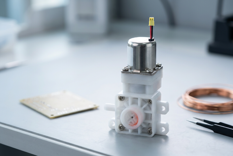
A connector that fits mechanically does not confirm electrical compatibility. Terminal assignments, insulation, wiring layout, and connection method should match the product instructions, since incorrect connections can block operation or damage parts. This is particularly relevant when a toilet system is supplied by one manufacturer but uses valves and controllers from different suppliers. Before installation, check the following points:
- The valve's connection method
- The controller's available outputs
- Terminal functions and wiring layout
- Any required intermediate switching parts
- Instructions for safe installation and inspection
Operating Logic and Response
Matching Valve Behavior
Valves do not all behave alike when power is applied or removed. Some open when energized and close when power ends, while others follow a different principle. A controller that expects the valve to stay open may not suit one built for brief activation. A valve needing a particular sequence may misbehave with a controller that sends another.
A useful review describes the expected valve state during normal operation, after a command ends, and when power is lost. Confirm this from product documentation and not from a general description.
Response in the Full System
The controller sends a command at a set moment, but water flow changes only when the valve mechanism responds. If response differs from what the controller expects, the flushing sequence drifts from its design. Water pressure, contamination, wear, and the condition of the electrical connection all influence response.
| System Element | Compatibility Question |
|---|---|
| Controller | Does it send the intended command? |
| Electrical interface | Does the signal reach the valve correctly? |
| Valve mechanism | Does it respond as expected? |
| Water supply | Does the condition suit the valve? |
| Flushing sequence | Does valve operation match the timing? |
Checking only that the valve opens once may miss problems that appear in repeated use.
Sensors
In an automated toilet, a sensor tells the controller when to flush, and the controller commands the valve. The valve usually does not connect to the sensor directly. Compatibility therefore covers the whole signal path. If the logic is unclear, the valve may receive a command at the wrong time or stay active longer than intended. Document how each component contributes so installers and service teams can follow it.
Choosing and Installing the Valve
Selecting an Inlet Valve
An Inlet Valve for Toilet may control water entering a tank, supply a flushing mechanism, or serve another function defined by the design. Some systems use electrically controlled valves, while others use mechanical arrangements. Identify the valve's role in the assembly so it is not chosen only because the name resembles the part being replaced.
Review water and electrical connections separately. A valve may fit the plumbing yet lack the needed electrical function. Product information should describe intended application, connection method, operating principle, and control requirements.
Wiring and Environment
Poor connections, unsuitable cable arrangements, or wrong terminals can interrupt the signal path. Toilet systems operate near moisture, so electrical connections need suitable protection. Route cables to avoid strain on connectors and to keep maintenance access clear, and follow the equipment's safety requirements and local installation rules.
Different Suppliers
Mixing suppliers gives flexibility but raises the need for checks. The valve maker may design for one control method while the controller supplier expects another load or sequence. Obtain documentation from both covering electrical requirements, signal behavior, connection details, and valve response when the command changes. Agree who verifies the integrated system, because a valve and controller can each pass their own tests and still behave differently together. For OEM and ODM projects, share the expected flush sequence, installation environment, and control arrangement early.
Testing and Documentation
Verification Steps
Test under the conditions specified for the application, by people with suitable knowledge and authorization. Inspect electrical connections before applying power and confirm water connections are suitable.
- Confirm valve and controller requirements match.
- Check wiring and interface connections.
- Verify the controller sends the intended command.
- Observe whether the valve opens and closes as designed.
- Check the flush sequence in normal conditions and over repeated cycles.
- Review behavior after a power interruption.
- Record any mismatch and confirm the correction.
The aim is to verify the complete sequence, not just that the valve can move.
Supplier Information
Useful documentation covers electrical supply, control method, connection layout, normal operating behavior, installation conditions, and maintenance needs. It should also flag conditions that could affect use with a particular controller. The same information helps technicians during replacement, since they can compare a new valve's requirements with the existing controller and not rely on the look of the old part.
Power, signals, interface, valve response, and controller logic together decide whether a Solenoid Valve for Toilet works in its system, while the Inlet Valve for Toilet must also suit the plumbing function and installation conditions.