
 EN
EN English
 Español


Purchasing a valve is straightforward enough. Making it behave predictably inside a live industrial system is where things get complicated. A fair number of engineers reach the commissioning stage only to find the unit unresponsive, switching erratically, or drawing power in ways that do not match expectations. The frustration is usually not about the hardware itself. A Bi Stable Solenoid Valve operates on a different electrical logic than many solenoid valves. Without recognizing that distinction upfront, integration problems are nearly guaranteed. The practical knowledge buyers need once the product is in hand, from wiring through to long-term system reliability, is outlined below.
How Does This Valve Actually Hold Its Position?
Many solenoid valves need continuous power to stay in an open or closed state. Cut the power, and the valve returns to its default position. A bi-stable design works differently. It uses a permanent magnet latching system to hold whatever position it was last switched to, without any ongoing current flowing through the coil.
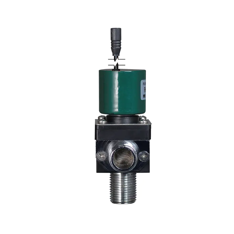
The implication for anyone setting up the control system is significant. Power is only consumed during the moment of switching. Once the valve has moved, the coil can be de-energized entirely and the valve stays put. This means the control circuit needs to output a timed pulse rather than a sustained signal. Holding voltage on the coil continuously is not just wasteful. Over time, it causes thermal stress that shortens coil life.
A few behaviors worth keeping in mind before wiring begins:
- Position is retained even after a full power loss to the system
- Two separate coil inputs handle each switching direction independently
- The valve generates no internal position feedback unless a sensor is added externally
- Pulse timing, not signal duration, determines whether switching completes successfully
Wiring: Where Many Integration Errors Occur
Getting Polarity and Coil Assignment Right
The valve body typically carries two coil connections, one for each direction of travel. Mixing them up does not always produce an obvious failure. Sometimes the valve simply refuses to switch in one direction, or it switches partially and stalls. Tracing that back to a wiring reversal after the system is already assembled takes considerably more effort than checking the diagram beforehand.
Before connecting anything:
- Match the supply voltage to the coil rating listed on the valve nameplate
- Pull up the manufacturer wiring diagram and identify which coil drives which direction
- Confirm the control circuit can either switch polarity or use two separate output channels
- Check that the ground reference is shared cleanly between the control board and valve terminals
A loose or floating ground is one of the more common causes of inconsistent switching behavior that looks like a valve fault but is actually an electrical one.
Does the Control Circuit Support Pulse Output?
Standard PLC digital outputs default to a maintained state, meaning they hold the signal high for as long as the command is active. That is not what a bi-stable solenoid valve needs. The output module has to be programmed to release after a defined time window, returning the signal to low once the switching pulse has been delivered.
Getting the pulse duration right takes a small amount of testing. A pulse that is too brief may not provide enough energy to complete the full stroke. One that runs too long wastes energy and generates unnecessary heat in the coil. The valve documentation will specify a recommended range. Testing within that range on the bench before live system integration is time well spent.
PLC Integration and Control Logic
Building the Switching Sequence
Because the valve carries no built-in position feedback, the PLC cannot independently verify where the valve is sitting at any given moment. The control logic has to be written with that limitation in mind, either by adding an external sensor or by designing the sequence around confirmed command outputs.
A workable control structure generally looks like this:
- A SET output triggers a timed pulse to the open-direction coil
- A RESET output triggers a timed pulse to the close-direction coil
- An interlock condition in the logic prevents both coils from receiving a signal at the same time
- A startup initialization routine sends a defined-direction pulse so the system begins from a known state
The interlock is not optional. Sending simultaneous pulses to both coils can cause unpredictable behavior and, in some valve designs, may stress the latching mechanism.
What Happens During a Power Cycle?
This is something that catches engineers off guard more often than it should. Because the valve holds its mechanical position through a power outage, it will be in whatever state it was last switched to when power returns. If the process requires the valve to start in a specific position, that needs to be handled explicitly in the startup logic with a deliberate initialization pulse.
Without that, the PLC may assume a default state that does not match the actual valve position. Depending on what the valve controls, that mismatch can cause downstream equipment conflicts or flow errors that take time to trace back to their source.
Installation Orientation and Flow Direction
Does the Flow Direction Matter?
It does, and it is one of the easier things to get wrong during a busy installation. Many bi-stable solenoid valves are unidirectional. Fluid is expected to enter from one specific side, and the internal geometry is designed around that assumption. Installing the valve backwards can restrict flow, create uneven pressure across the seals, or in some cases prevent the valve from reaching full actuation.
The flow direction arrow on the valve body is there for a reason. Before threading the valve into the line:
- Check the arrow and confirm it aligns with the actual flow direction in the pipe
- Match thread type and size to the existing fittings before applying any sealant
- Tighten to the torque range specified in the documentation, not by feel
Over-tightening is a surprisingly common cause of seal distortion that only shows up as a slow leak weeks after installation.
Mounting Position and Vibration
Some latching valve designs are position-sensitive, particularly if gravity plays any role in how internal components seat. Vertical mounting may be required, or it may be restricted, depending on the internal design. The installation sheet will specify this.
Vibration is a separate concern. In high-vibration environments, the valve body should be secured with appropriate bracket hardware, and flexible connections should be used on the pipe side where possible. Rigid connections that transfer mechanical stress directly to the valve body can gradually affect sealing surfaces and internal alignment over extended operating periods.
System Compatibility Check Before First Run
Prior to energizing the valve, a structured compatibility check reduces the chance of encountering problems during commissioning that could have been caught earlier. Working through the following parameters takes only a short time and avoids a much longer troubleshooting process later.
| Parameter | What to Verify |
|---|---|
| Supply voltage | Confirmed match with coil rating |
| Pulse duration | Falls within the manufacturer's specified window |
| Fluid medium | Chemically compatible with seal and body materials |
| Operating pressure | Stays within the valve's rated pressure range |
| Fluid temperature | Does not exceed the seal material's rated limit |
| Control circuit output | Capable of delivering timed pulse per coil channel |
| Mounting orientation | Matches the installation requirement in the datasheet |
Each item on this list represents a failure mode that shows up regularly in post-installation troubleshooting reports. Addressing them before the system goes live is a straightforward way to avoid that category of problem entirely.
Energy Efficiency: Are You Actually Using the Advantage?
The Benefit Only Works If the Wiring Is Correct
One of the more compelling reasons engineers specify a bi-stable solenoid valve over a conventional alternative is the reduced energy consumption. Because current only flows during switching events, the cumulative power draw across a system with many valve cycles can be substantially lower than a continuously energized design.
That advantage only materializes if the control circuit is actually releasing the coil signal after each pulse. If the output is staying high between switching events, the valve is effectively running as a continuously energized device and the efficiency benefit is gone. Checking current draw at the valve terminals during steady-state operation is a quick way to confirm the control logic is behaving correctly.
Long-Term Maintenance and Reliability
What Actually Causes Valve Failure Over Time?
Bi-stable solenoid valves tend to have relatively long service intervals compared to continuously energized alternatives, largely because the coil is not under constant thermal load. That said, they do wear, and the failure modes follow a recognizable pattern.
The components that show degradation earliest are typically:
- Seals, particularly when the fluid medium carries fine particulate or has chemical properties near the edge of compatibility
- Coil windings, in installations where voltage spikes from adjacent equipment are common and no surge suppression has been fitted
- The latching mechanism itself, in cases where contamination has entered the valve body through a degraded seal
Valves installed in systems where switching happens infrequently sometimes develop seal stiffness simply from sitting in one position for extended periods. Building a periodic test cycle into the maintenance schedule, where the valve is cycled through both positions deliberately, helps prevent that.
A Practical Maintenance Schedule
Reactive maintenance on fluid control components tends to be more disruptive and costly than scheduled inspection. A structured approach for a bi-stable solenoid valve typically includes:
- Visual checks of coil terminals and housing at regular intervals, looking for corrosion, moisture ingress, or physical damage
- Functional switching tests as part of broader system diagnostics, monitoring response time for any degradation trend
- Seal replacement on a defined schedule or immediately upon any sign of external leakage
- Upstream filtration checks to confirm that fluid cleanliness remains within the specification for the valve's seal material
In applications where the valve sits at a critical point in the flow path, adding a position feedback sensor gives the control system visibility into switching failures before they affect the process.
Troubleshooting: When the Valve Does Not Respond as Expected
Why Might the Valve Fail to Switch?
Switching failures in bi-stable solenoid valves are more often electrical in origin than mechanical. Before pulling the valve out of the line, it is worth working through the control circuit systematically.
A practical diagnostic sequence:
- Use a multimeter to confirm the pulse signal is actually reaching the coil terminals during a switching command
- Verify the pulse duration falls within the range specified for the valve
- Check the logic to confirm both coils are not being triggered at the same moment
- Monitor supply voltage during the switching pulse to rule out voltage drop under load
- Inspect the valve inlet for contamination or debris that could be opposing actuation mechanically
If the valve responds to a manual override but not to the electrical signal, the problem is in the control circuit. If it fails to actuate mechanically as well, internal inspection for seal damage or contamination is the next step. Keeping a record of switching behavior over time makes it considerably easier to distinguish a sudden failure from a gradual decline.
Choosing the Right Support Partner Matters
Getting the hardware right is only part of the picture. A valve that arrives without clear technical documentation, or where the supplier is difficult to reach during commissioning, puts the full burden of integration onto the engineering team. That adds time and risk to what should be a straightforward process. Zhejiang Fuxin Electrical Technology Co., Ltd. manufactures bi-stable solenoid valves and provides technical support covering electrical integration, PLC compatibility, pulse control configuration, and fluid medium suitability. For buyers working through installation or facing application-specific questions about how the valve fits into an existing control architecture, engaging the technical team early in the process tends to surface answers before they become problems on the floor. Providing clear details about the operating environment, control system type, and fluid conditions allows their engineers to give recommendations that are grounded in the actual application rather than general guidance. If you are at the integration stage and have unresolved questions, reaching out directly is the practical next step.